The invention provides a walking device which stimulates a gait of a legged animal. The device includes a frame with spaced axial mounts, a leg, axially connected upper and lower rocker arms which limit reciprocating leg motion. The leg is driven by a connecting arm powered by a rotating crank. The position and configuration of the axial connecting sites establish a prescribed orbital path that the foot undertakes with each revolution of the crank. Both rocker arms and the crank are axially mounted to the frame.
The leg has a hip joint axially connected to the upper rocker arm for limiting hip motion, a foot and a knee joint axially connected to the connecting arm. The connecting arm has three axial connecting sites, one for connecting to the knee, another to the crank, and a third connecting site defined as a centrally disposed elbow joint connecting site which connects onto the lower rocker arm and limits knee joint motion. Under power, crank rotation is transferred to the connecting arm causing the leg to move in an accurate reciprocating movement of a restricted actual pathway which stimulates the gait of the legged animal.
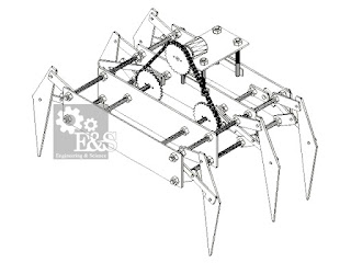
The walking device may be manually powered or motorized by applying motorized power to the crank axles. Klann mechanism is a planar mechanism designed to simulate the giant legged animal and function as a wheel replacement. Here we are using a single leg consists of a six – bar linkage made up entirely of pivot joint that converts rotating motion into linear motion. The linkage consists of the frame, a crank, two grounded rockers, and two coupler is connected using pivot joints. The proportions of each of the links in the mechanism are defined to optimize the linearity of the foot for one-half of the rotation of the crank.The remaining rotation of the crank allows the foot to be raised to a predetermined height before returning to the starting position and repeating the cycle. Two of these linkages coupled together at the crank and one-half cycle out of phase with each other will allow the frame of a vehicle to travel parallel to the ground.
The Klann linkage provides many of the benefits of more advanced walking vehicles without some of their limitations. It can step over curbs, climb stairs, or travel into an area that are currently not accessible with wheels but does not require microprocessor control or multitudes of actuator mechanisms.


It is also applicable in the goods industries for the small transportation of goods inside the industry. The mountain roads or other difficulties where ordinary vehicles cannot be moved easily can be replaced by our six leg mechanical spider. Heavy loads can be easily transported if we made this as a giant one. It has got further application for the study of linkage mechanism and kinematic motions. The geometry and conditions can be changed according to application needs. It can travel in rough surfaces very easily, so this machine can be used in rough surfaces were ordinary moving machine cannot travel.
The leg has a hip joint axially connected to the upper rocker arm for limiting hip motion, a foot and a knee joint axially connected to the connecting arm. The connecting arm has three axial connecting sites, one for connecting to the knee, another to the crank, and a third connecting site defined as a centrally disposed elbow joint connecting site which connects onto the lower rocker arm and limits knee joint motion. Under power, crank rotation is transferred to the connecting arm causing the leg to move in an accurate reciprocating movement of a restricted actual pathway which stimulates the gait of the legged animal.
The walking device may be manually powered or motorized by applying motorized power to the crank axles. Klann mechanism is a planar mechanism designed to simulate the giant legged animal and function as a wheel replacement. Here we are using a single leg consists of a six – bar linkage made up entirely of pivot joint that converts rotating motion into linear motion. The linkage consists of the frame, a crank, two grounded rockers, and two coupler is connected using pivot joints. The proportions of each of the links in the mechanism are defined to optimize the linearity of the foot for one-half of the rotation of the crank.The remaining rotation of the crank allows the foot to be raised to a predetermined height before returning to the starting position and repeating the cycle. Two of these linkages coupled together at the crank and one-half cycle out of phase with each other will allow the frame of a vehicle to travel parallel to the ground.
The Klann linkage provides many of the benefits of more advanced walking vehicles without some of their limitations. It can step over curbs, climb stairs, or travel into an area that are currently not accessible with wheels but does not require microprocessor control or multitudes of actuator mechanisms.
PHOTOS & DRAWINGS


APPLICATIONS
It would be difficult to compete with the efficiency of a wheel on smooth hard surfaces but as condition increases rolling friction, this linkage becomes more viable and wheels of similar size cannot handle obstacles that this linkage is capable of. Toys could be developed that would fit in the palm of your hand and just large enough to carry a battery and a small motor. Six leg mechanical spiders can be applicable for the making of robots. It has a wide range of application in the manufacturing of robots. A large version could use existing surveillance technology to convert your television into a real-time look at the world within transmitting range. It would also relay commands from the remote to the spider bike additional frequencies could be used to operate manipulators for retrieving the mail during unfavorable weather or taking the dog out. In toy industries for making robotic toys it has got many applications. It can also be used for military purpose. By placing bomb detectors in the machines we can easily detect the bomb without harmful to humans. It can be used as heavy tanker machines for carrying bombs as well as carrying other military goods.It is also applicable in the goods industries for the small transportation of goods inside the industry. The mountain roads or other difficulties where ordinary vehicles cannot be moved easily can be replaced by our six leg mechanical spider. Heavy loads can be easily transported if we made this as a giant one. It has got further application for the study of linkage mechanism and kinematic motions. The geometry and conditions can be changed according to application needs. It can travel in rough surfaces very easily, so this machine can be used in rough surfaces were ordinary moving machine cannot travel.
ADVANTAGES
- Construction expense is low.
- Heavy load can be carried.
- It can be run in rough surfaces
- Easy to control Maintenance is less
DISADVANTAGES
- Speed is minimum due to load.
- Not smooth running.
- High powered motor is needed.
It looks like the drawings can't possibly work!
ReplyDeleteBut its working dude. Watch the video carefully
DeleteI also don't see how it can work from the drawings. It seems that the rotating crank and a part of the leg should run into each other at some point of the rotation. Maybe I am looking at it wrong. Can you help me understand?
Deletesir i am not able to calculate the dimensions please explain about klenn mechanism dimensions calculation
ReplyDeletesorry sir we are not authorised to provide you details like dimentions at this time
Deletehow many watt motor do we require to make this
ReplyDeleteMotor specification depends on factors of your system like total weight, Motor must have the power to lift the system without any starting trouble.
Deletewithout using sensors how can we turn this??
ReplyDeletethis model is basic & need more modification. in the upgraded model we can use sensors to turn the device.
Deletetry to extend this project buddy!
which motor is used in this project? And admin can you post a link to download the project file of mechanical spider?
ReplyDeletematerial used???????
ReplyDeletewhat is the power/rpm of moter you have used in this project
ReplyDeleteSimilar to Six leg kinematic moving machine in appearance but entirely different mechanism. Works great dude. :)
ReplyDeletethat's awesome :)
ReplyDeletecan you please tell us the type of motor used in this project...
ReplyDeletepls..send..the..rpeort..of..tis.project
ReplyDeleteSo many lazy...so called engineers. Dudes, do just like the american...build it and epxeriment...don't just wait to be spoon fed! Your are not babies!!!
ReplyDeleteCan i get the countact no.. If I want to contact with you
ReplyDeleteCan I know the dimensions of the parts you made? We want to build a robot like yours for a school project.
ReplyDeleteTo reach me, you can reach me via senolkoray65@gmail.com.